¶ Screen Connection
¶ 1. Overview
This document provides a comprehensive guide for the installation, configuration, and operation of the NovaLCT screen connection part.
- Key Features: Briefly describe how to use NovaLCT to configure a screen.
¶ 2. Software Configuration and Operation Guide
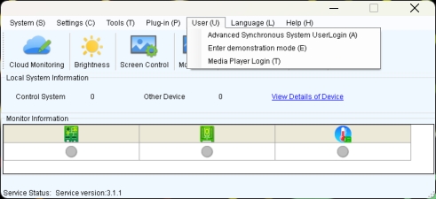
¶ 2.1. User login
- When the device is from the MCTRL, VX, VX Pro, H, MEE, KT series, select "Advanced Synchronous System User Login," with the default password set as "admin."
- When the device is from the TB, TU, or JT series, first connect to the AP Wi-Fi named by device's SN. The default password is either "12345678" or "SN2008@+", then select "Media Player Login." The default account is "admin," and the default password is either "123456" or "SN2008@+".
¶ 2.2. Screen connection
¶ 2.2.1 Standard Screen Connection
- Click "Screen configuration," then select the corresponding device IP or COM port, and click Next to enter the “Screen Connection” configuration interface.
- Take a 3x3 LED screen as an example, the resolution of a single cabinet is 480x270.As shown in the figure below.
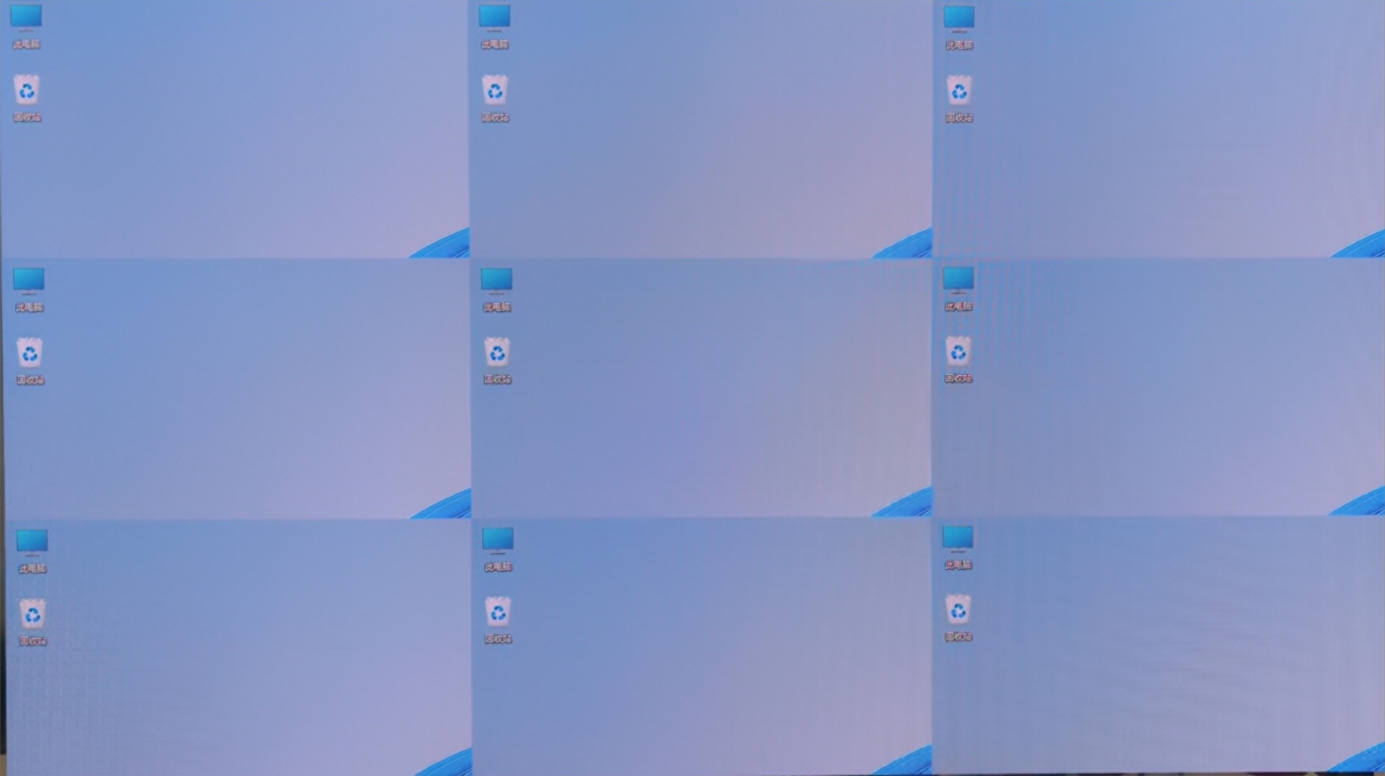
- Enable Mapping to view the physical arrangement of the cabinet.9(
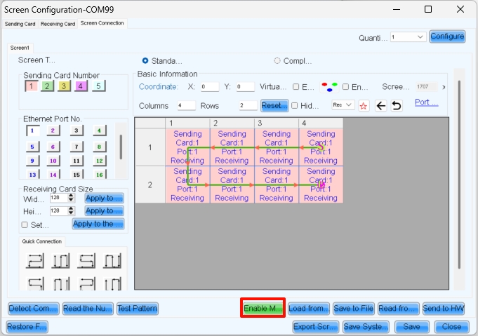
- Here, S represents the sending card number, P indicates the network port number on that sending card, and # denotes the cabinet number under that port. For example, S:01 P:04 #002 means the second cabinet connected to network port 4 of the first sending card.
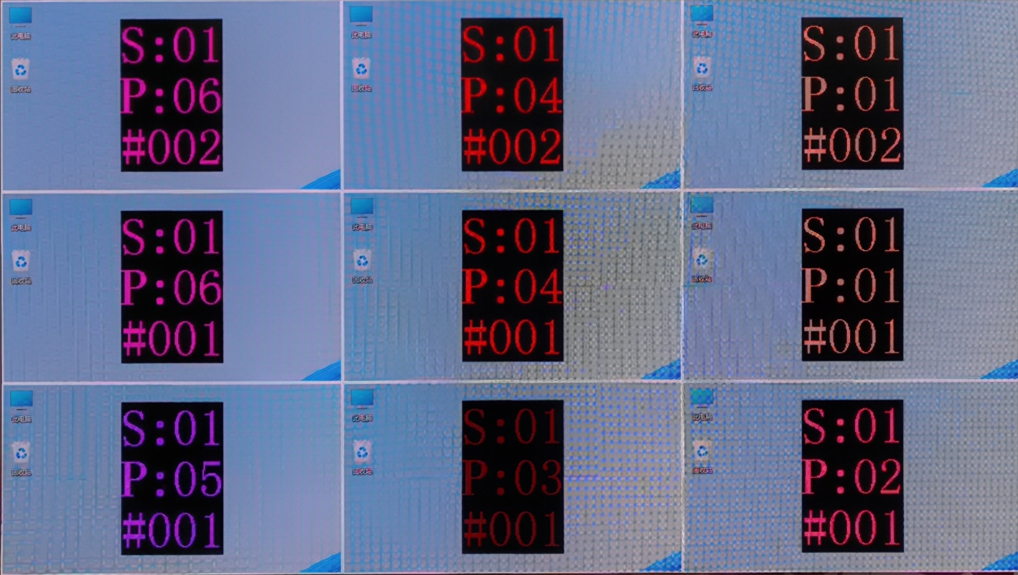
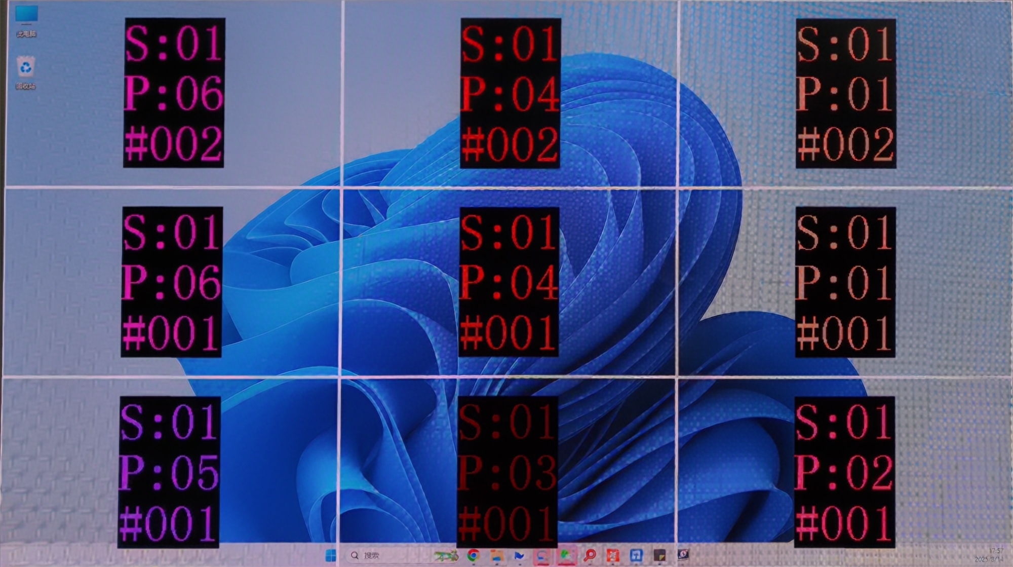
- Complete the cabinet connection according to the front view.
- After sending and saving, the screen will display as a completed image.Then disable Mapping.
¶ 2.2.2 Complex Screen Connection
Here is a example for complex screen connection
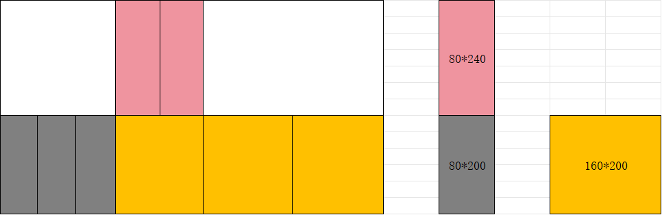
In complex screen mode, screen connection requires coordinate settings.
Complex Screen Connection is only for devices like the MCTRL series and TB series. If your project is important and large-scale, we recommend choosing the VX PRO series and COEX series.
In the screen connection interface, select the complex screen.
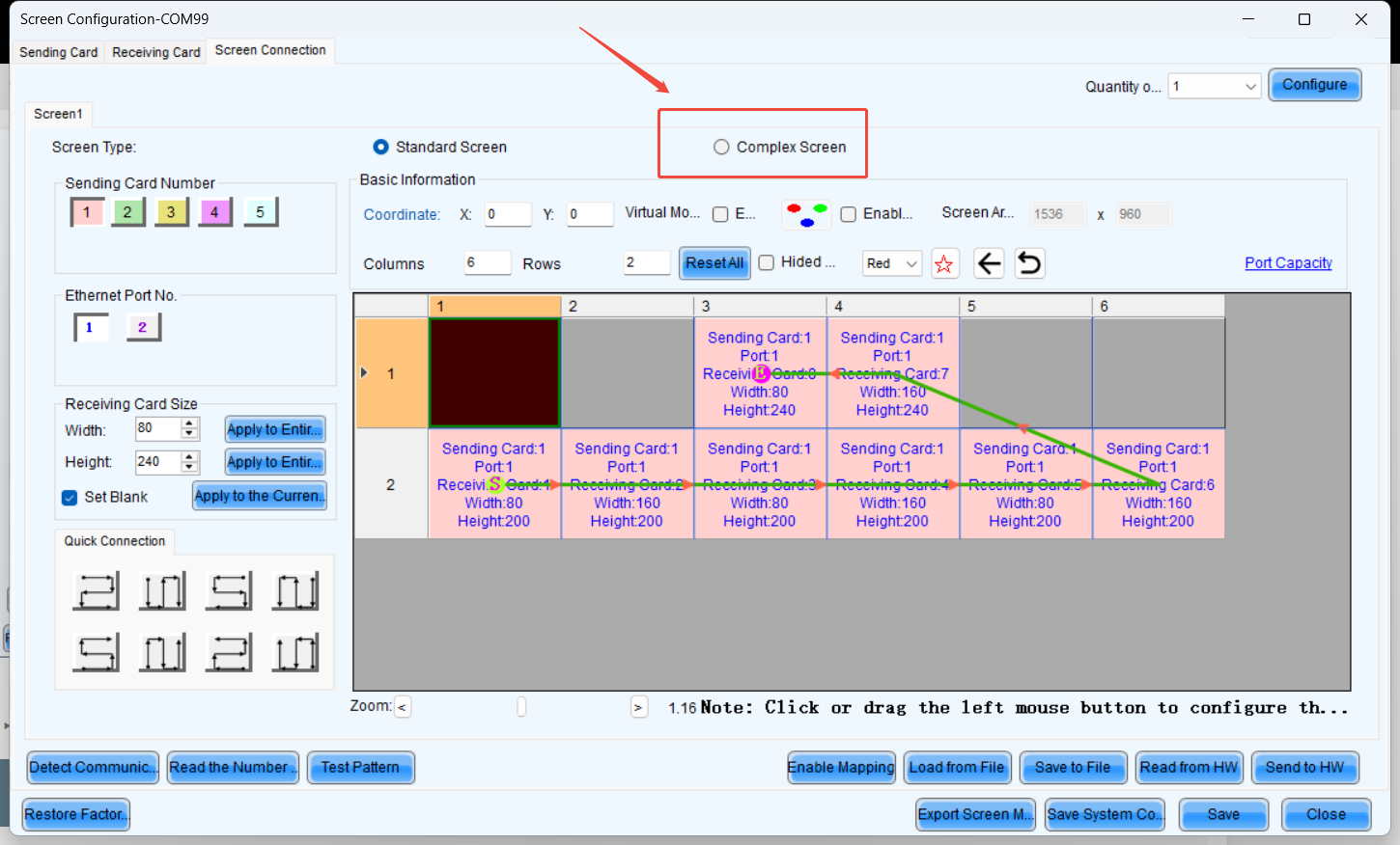
Since the height of the upper half is 240 pixels, the coordinates of receiving card 1 are (0, 240).
Similarly, the coordinates for receiving card 2 should increase by the width of receiving card 1 (80 pixels) along the X-axis.
Therefore, the coordinates for receiving card 2 are (80, 240).
The coordinate calculation logic for the remaining receiver cards remains the same as that of 1 and 2.
NOTE : Complex Screen Connection still has a rectangular load limit.
You also can move blocks with your mouse to align them.
¶ 3. Troubleshooting
3.1 The second output card of the H series displayed a black screen, but the screen control was functioning normally.
- Ensure that when does H-series screen connection, each output card corresponds to one screen. For example, if we use an H2 to drive a 7680x2160 screen, with each output card handling 3840x2160, the screen connection setup would look like below, ensure that the coordinates of all output cards start from (0, 0).
- The reason is that if multiple cards are configured within a single screen, all output cards except the first one on the left will experience coordinate offset. Additionally, Hweb will perform a splicing operation, causing a secondary coordinate shift and resulting in black screen issues.